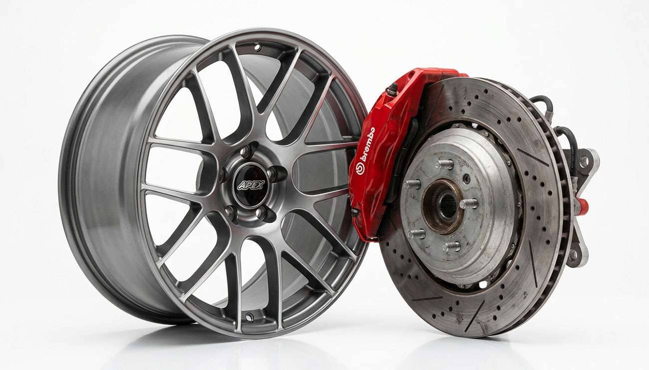
Caliper clearance is not one measurement. It is three, and the one that fails is almost never the one people check. Diameter controls radial clearance at the barrel. Offset and spoke profile control lateral clearance at the spoke face, and that is where most fitments actually make contact. Spoke profile depth is the number that decides it, and no wheel manufacturer publishes it. Most guides tell you to print a caliper template and hedge the rest. The part nobody puts in front of you is which of the three planes your setup is tight in, because the fix is different for each one.
You measure three separate gaps, all referenced from the same datum: the flat machined face of the wheel that bolts against the hub. That surface is the mounting pad, and it is the only part of a wheel whose position is fixed by the vehicle rather than by the wheel's design.
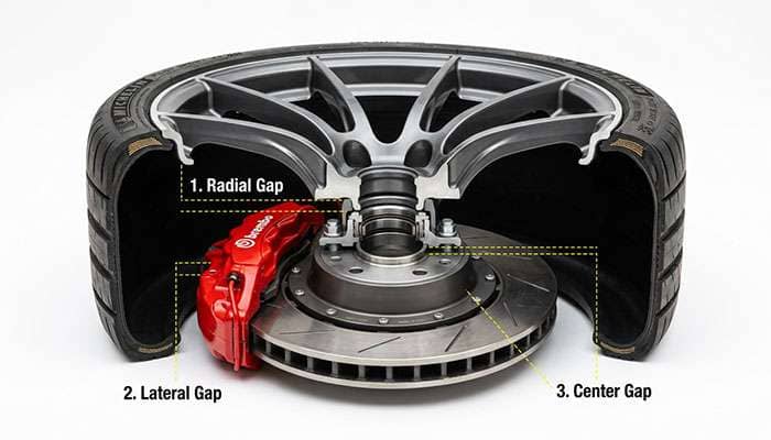
Radial clearance is the gap between the tallest point of your caliper and the inside of the wheel barrel, measured out from the axle centerline. This is the one everybody checks, because it scales with diameter. Go from a 17-inch wheel to an 18-inch wheel and you gain roughly half an inch of radius at the barrel.
Lateral clearance, sometimes called axial clearance, is the gap between the outboard face of the caliper body and the inboard face of the wheel's spokes. This is the plane that fails most often, and it has nothing to do with diameter. It is set by offset, which moves the whole wheel inboard or outboard, and by how deeply the spokes are dished behind the mounting pad.
Mounting pad and hat clearance is the gap at the center, where the back of the mounting pad and the edge of the center bore sit against the rotor hat and, on some designs, the caliper bridge. Thick pads and undersized bores interfere here even when the outer two planes are fine.
Use the table below to work out which plane your build is tight in.
Symptom or Setup |
Plane That Is Tight |
What Controls It |
What Actually Fixes It |
|---|---|---|---|
Wheel will not seat flat against the hub; gap at the pad |
Mounting pad or hat |
Pad thickness, center bore diameter, rotor hat height |
Correct bore size or a hub-centric ring; never a spacer alone |
Wheel seats flat but will not rotate; scrape at the outer rim edge |
Radial |
Wheel diameter and barrel drop |
Larger diameter wheel, or a wheel with a less aggressive barrel step |
Wheel rotates but a spoke ticks once per revolution |
Lateral, at one spoke |
Spoke profile depth at that radius |
Different spoke design, or more positive offset |
Steady drag or rub with no clean tick; heat at one corner |
Lateral, full contact |
Offset and caliper body width |
More positive offset wheel; spacer only as a measured last resort |
Clears on the lift, rubs under load or hard cornering |
Lateral, dynamic |
Wheel deflection under load; gap was under 3mm static |
Restore 3mm minimum static clearance; stiffer wheel construction |
Cleared when new, started ticking months later |
Lateral, migrating |
Floating caliper sliding outboard as the outer pad wears |
Measure clearance with worn pads, not new ones |
That last row catches experienced people. Most clearance advice assumes the caliper sits still, and on the majority of passenger vehicles it does not.
Three millimeters in every direction, measured static, with the pads worn rather than new. That figure gets quoted without the reasoning, so here it is.
There is no federal number to point to. NHTSA administers FMVSS 135, the light vehicle brake systems standard, which governs stopping distance, pedal effort, and system performance. It says nothing about how close a wheel may sit to a caliper. SAE J2530, the aftermarket wheel performance standard, covers fatigue and impact testing of the wheel itself, not its relationship to the brake package. Wheel-to-caliper clearance is an engineering practice carried over from OE packaging, not a regulated dimension, which is why published guidance varies between 2mm and 3mm.
Three millimeters is the defensible number because four things eat into a static gap:
Thermal growth. A cast iron rotor and an aluminum caliper both expand when hot, and aluminum expands roughly twice as much as iron for a given temperature rise. The caliper you measured cold is physically larger after a mountain descent.
Wheel deflection under load. A wheel is not rigid. Under hard cornering the loaded side flexes toward the vehicle centerline, and cast one-piece wheels deflect more than forged. This is the mechanism behind the most frustrating complaint in fitment, where a wheel spins freely on the lift and ticks only in a fast corner.
Runout. Bearing play, worn bushings, and a slightly bent rotor hat all introduce small irregularities that close the gap intermittently rather than constantly.
Pad wear on floating calipers. This is the big one, and the next section covers it.
Under 3mm you are relying on all four staying small at once. At 3mm or more, ordinary variation has somewhere to go.
Most passenger cars and light trucks use a floating, or sliding, caliper, with the piston on the inboard side only. Press the pedal and the piston pushes the inner pad against the rotor, and the reaction force slides the caliper body inboard on its guide pins, pulling the outer pad in from the other side.
Here is the consequence nobody mentions in a clearance guide. As the outboard pad wears down, the caliper body floats progressively further outboard to keep that pad in contact with the rotor face. Its resting position migrates toward your wheel spokes across the life of the pads. Measured with fresh pads, a caliper sits at its innermost position. By the time the outer pad nears its wear limit, that caliper's outboard face has moved measurably closer to the spoke.
Fixed calipers, the opposed-piston type used on most big brake kits and performance OE packages, do not do this. The body is bolted to the upright and never moves, so clearance measured cold with new pads is the clearance you keep.
The practical instruction: if your calipers float and your pads are new, treat your measured lateral clearance as the best case rather than the number. Measure again with worn pads, or add a few millimeters of margin.
Because diameter, width, and offset describe where the wheel sits. They say nothing about the shape of the metal between the mounting pad and the rim.
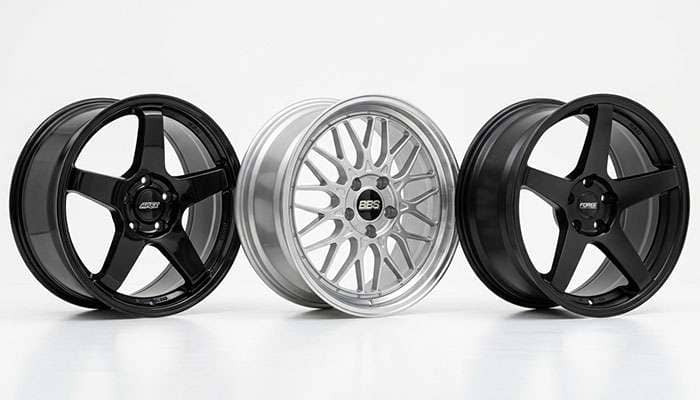
Well over two hundred distinct wheel models are sold in the single specification 18x8 with a +35mm offset. Every one mounts in exactly the same position on exactly the same hub. They do not clear the same brakes. A deep-concave five-spoke, a flat-face mesh, and a stepped-lip split-spoke in that identical size present completely different obstacles to a caliper, because the inboard surface of the spoke sits at a different depth on each, and that depth changes as you move outward along the spoke.
That dimension has a name in engineering drawings and none at all on a product page. Look through any wheel catalog and you will find diameter, width, offset, bolt pattern, hub bore, load rating, construction, and finish. There is no field for caliper clearance, because the industry never created one. Backspacing, the older measurement describing how far the mounting pad sits from the inboard rim edge, has largely vanished from modern listings in favor of offset, and even it would not tell you the spoke profile.
So the honest answer to "will this wheel clear" is that the published specification cannot tell you. Two wheels with identical numbers can differ by ten millimeters or more at the spoke face. You are measuring the wheel, not reading about it. Some patterns do narrow the field before you measure:
Wheel Characteristic |
Effect on Caliper Clearance |
Best Suited To |
|---|---|---|
Flat-face or slightly convex spoke |
Most generous lateral clearance for a given offset |
Big brake kits, upgraded OE performance calipers |
Deep concave or dished spoke |
Spoke sweeps inboard toward the caliper; tightest at mid-radius |
Stock or compact calipers only; measure before committing |
Mesh or multi-spoke with many contact points |
More opportunities for a single spoke to interfere |
Stock brakes; template check strongly advised |
Forged or flow-formed construction |
Thinner spoke sections and less deflection under load |
Track use and tight-clearance big brake builds |
Cast one-piece, the aftermarket majority |
Thicker spoke sections; more flex, so needs more static margin |
Street builds with 3mm or better measured clearance |
More positive offset, same diameter and width |
Moves the entire wheel outboard, away from the caliper |
Gaining lateral clearance without changing diameter |
Construction is worth weighing if you are near the limit. Forged and flow-formed wheels reach their strength with less material, which means thinner spokes and a flatter inboard profile in the same nominal size, and they deflect less under load. On a tight build that can be the difference between clearing and not.
Both, in completely different directions, and confusing them is the most expensive mistake in this subject.
Diameter works radially. A larger wheel puts the barrel further out from the axle centerline, giving a tall caliper more room to pass underneath. It does nothing to the lateral position of the spoke face.
Offset works laterally. Offset is the distance from the mounting pad to the wheel's centerline. Increase it toward positive and the wheel is pulled outboard on the vehicle, opening the gap at the caliper. Decrease it toward negative and the wheel moves inboard and closes that gap.
Here is where people lose money. Somebody fits a big brake kit, finds it does not clear, and buys a larger diameter wheel to solve it. If the interference was radial, at the top of the caliper against the barrel, that works. If it was lateral, at the spoke face against the caliper body, the new larger wheel in the same offset fails in exactly the same place, because nothing moved in the direction that mattered.
The spread available in offset is larger than most people assume. Within a single popular size, market offsets run from deeply negative to strongly positive, spanning well over a hundred millimeters. Two wheels both honestly described as 18x8 can place the spoke face nearly two inches apart. That is your adjustment range. Our guide to wheel offset, backspacing, and bolt patterns explained covers how to compare those numbers, and concave wheel clearance gets into how spoke profile interacts with them.
One caution. Offset is not a free variable. Moving a wheel outboard changes scrub radius, loads the wheel bearing differently, and can introduce fender contact at full lock or full compression. Chasing caliper clearance with offset alone, without checking the outboard side, trades one rub for another. That is common enough after a fitment change that we covered why your tires are rubbing separately.
You need a straight edge long enough to span the hub, a steel ruler or caliper reading millimeters, and about twenty minutes per axle. Do front and rear separately, because the brake packages usually differ.
Step one. Support the vehicle and remove the wheel. Chock the wheels staying on the ground, lift at the manufacturer's jacking point, and support on stands rated for the load. Never measure under a jack alone.
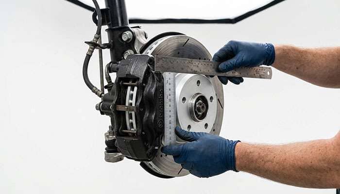
Step two. Establish your datum. Lay the straight edge flat across the hub mounting face so it sits on the machined surface and not on a stud or the rotor hat. Everything from here is measured from that plane.
Step three. Measure caliper height, the radial number. From the hub center, measure out to the furthest point of the caliper. Include the bleeder screw, the brake line fitting, and the anti-rattle clips. People measure to the caliper casting and then discover the bleeder is the tallest thing on the assembly. This is your minimum required wheel inner radius, and you want at least 3mm more.
Step four. Measure caliper depth, the lateral number. With the straight edge still across the hub face, measure back from it to the outboard face of the caliper body at its closest point. Note the radius where you measured, because the spoke profile changes as you move outward.
Step five. Measure the rotor hat. Take its outside diameter and its height above the hub face. That gives you the minimum center bore and maximum mounting pad thickness the wheel can have.
Step six. Check the wheel against those numbers. If you have the wheel, set it face down and measure inward from the mounting pad to the spoke face at several radii, comparing each to your step four number plus 3mm. If you do not have it yet, most brake kit manufacturers publish a full-scale clearance template. Print at exactly 100 percent, verify the printed scale against its own reference dimension with a ruler before trusting it, cut it out, and test fit inside the wheel.
Step seven. Verify under rotation. Once fitted, spin the wheel by hand through several revolutions and listen. One tick per revolution means a single spoke is contacting. Torque to the vehicle specification in a star pattern, then drive at low speed in an empty lot with the windows down before going near traffic. The Tire Industry Association publishes wheel service and torque procedures worth following, because an improperly seated wheel can mimic a clearance problem.
Fitting wheels over a brake conversion rather than factory brakes follows the same sequence with tighter tolerances. Our walkthrough of disc brake conversion wheel fitment covers the cases where a conversion moves the hub face as well as the caliper.
Sometimes, and the deciding factor is usually not what people expect.
Factory wheels are packaged around the factory brake system with modest margin, and manufacturers frequently share a design across trim levels carrying different brake packages. So the base-model wheel on a vehicle also sold with an optional performance brake package often has more room than it looks like. The reverse holds too: it may have no allowance at all for anything larger.
Big brake kits are specified by the minimum wheel diameter they require, which is a radial figure. That is necessary and not sufficient. A kit listed as requiring an 18-inch minimum will clear the barrel of any honest 18-inch wheel, but the kit maker cannot know your spoke profile, so the diameter requirement covers one of the three planes. That is why every reputable kit manufacturer also supplies a template.
Fixed multi-piston calipers, which is what most kits use, are typically wider than the floating caliper they replace. Lateral clearance therefore gets tighter even as radial clearance improves. That is the trap: the wheel that cleared your stock brakes with room at the barrel can fail at the spoke on a kit that meets the diameter specification perfectly.
The upside is that a fixed caliper does not migrate with pad wear, so confirmed clearance stays confirmed. For the full sequence on planning an installation around your existing wheels, see our big brake kit wheel clearance guide.
A spacer moves the wheel outboard, so it does increase lateral clearance. It is a legitimate solution when specified correctly and a genuine hazard when it is not.
What it fixes: lateral interference only. It moves the mounting pad outboard by its own thickness, opening the gap at the spoke face by that same amount.
What it does not fix: radial interference. If the caliper is too tall for the barrel, a spacer moves the wheel sideways and the caliper is still too tall. It also does nothing for a bore too small for the rotor hat.
What it costs: every millimeter outboard increases the bending moment on the wheel bearing and the leverage on the studs. It changes scrub radius, which alters steering feel and how the vehicle reacts to a brake imbalance. On thin spacers the original studs may no longer engage the lug nuts to full thread depth, and thread engagement is what holds your wheel on.
The rules that make spacers defensible are straightforward. Use hub-centric spacers that locate on the vehicle hub and provide a new register for the wheel, never lug-centric ones. Anything above roughly 20mm should be a bolt-on type with its own pressed studs rather than a slip-on shim. Confirm full thread engagement, generally at least the stud diameter's worth of thread. Retorque after the first fifty to one hundred miles. And if a spacer is the only thing making a fitment work, a wheel with more positive offset is usually the better answer, because it achieves the same lateral shift without adding a joint to the assembly. Our breakdown of whether wheel spacers stop tire rubbing covers sizing and hardware in more depth.
It escalates in a predictable order. This is what the gap is buying you.
First, cosmetic contact. A witness mark on the inboard face of one spoke, usually found during a tire rotation rather than heard. The fix at this stage is free: identify which plane is tight and correct it.
Then coating failure and corrosion. Contact removes the powder coat or clear from the spoke and the anodizing from the caliper. Bare aluminum in a wheel well collects road salt and brake dust, and corrosion spreads outward under the intact coating where touching up the finish cannot reach it.
Then material removal from the wheel. Steady contact machines away spoke material at a point of high stress concentration. Spokes are the load path between the rim and the mounting pad, so thinning one is not cosmetic, and no reputable shop will repair a load-bearing spoke that has been ground down.
Then brake system damage. Contact against the caliper body can damage a bleeder screw, a hard line fitting, or a dust boot. A compromised boot lets water and grit into the piston bore, which leads to a sticking piston, uneven pad wear, and a pull under braking. This is where a wheel problem becomes a braking problem.
Then heat and imbalance. A spoke riding a caliper adds parasitic drag at one corner. That corner runs hotter, its pad and rotor wear faster, and the vehicle develops an imbalance you feel as a pull and the stability system reads as a fault.
Finally, structural failure. A wheel with a thinned spoke, loaded by a pothole or a hard corner, can crack at the contact point. The SAE J2530 fatigue and impact testing an aftermarket wheel passes at the factory is testing an undamaged wheel. None of that certification survives material being machined off a spoke in service.
This ladder is worth spelling out because the early rungs are quiet. A witness mark makes no noise, and the same "I will keep an eye on it" reasoning people apply to tire sidewall damage and whether it is safe to drive applies here, with the same problem: the part is degrading on a schedule you cannot see, and the failure at the end is not gradual. Correcting it early costs a wheel swap. Correcting it late costs a wheel, a caliper rebuild, pads and a rotor, and a wheel bearing if it ran hot long enough.
The question "will these wheels clear my calipers" has a specific answer, and it is not on the spec sheet. Diameter, width, and offset tell you where the wheel sits. They do not tell you the shape of the spoke that has to pass the caliper, and that shape decides the majority of failed fitments.
Work the three planes. Measure caliper height from the hub center for radial clearance, caliper depth from the hub face for lateral clearance, and the rotor hat for pad and bore clearance. Hold 3mm minimum in every direction, measure with worn pads if your calipers float, and remember that a larger diameter wheel only solves a radial problem.
If you know your three numbers and want help matching them to a wheel that actually fits, our fitment team works from measurements, not guesswork. Browse wheels at Performance Plus Tire and bring your caliper dimensions with you. We have been sorting out fitment questions like this one in Long Beach since 1971, and a five-minute conversation before you order is a great deal cheaper than a set of wheels that ticks.
At least 3mm in every direction, measured static with the brake pads worn rather than new. No federal standard specifies this figure. It comes from OE packaging practice, and it exists to absorb thermal expansion of the rotor and caliper, wheel deflection under cornering load, and normal runout. Gaps under 3mm frequently clear on a lift and contact under load.
Only if the interference is radial, meaning the caliper is too tall for the wheel barrel. Increasing diameter moves the barrel further from the axle centerline but does not move the spoke face laterally at all. If a spoke is contacting the side of the caliper body, a larger wheel in the same offset will contact in exactly the same place. Lateral interference is corrected with more positive offset or a different spoke profile.
With the wheel off, measure three things from the hub mounting face: hub center to the furthest point of the caliper including the bleeder screw, the hub face back to the caliper's outboard face, and the rotor hat diameter and height. Add 3mm to each. Then get a full-scale clearance template from the brake or wheel manufacturer, verify the print scale with a ruler, and test fit it inside the wheel before ordering.
Yes, for lateral interference only. A spacer moves the wheel outboard by its thickness and opens the gap at the spoke face by that amount. It does nothing for a caliper too tall for the barrel or a bore too small for the rotor hat. Use hub-centric spacers, choose a bolt-on type with pressed studs above roughly 20mm, confirm full lug nut thread engagement, and retorque after fifty to one hundred miles.
Because your static clearance was too small to survive load. A wheel flexes toward the vehicle centerline under hard cornering, and cast one-piece wheels deflect more than forged. The rotor and caliper also grow as they heat, with aluminum expanding roughly twice as much as iron. A gap measuring 1mm cold on a lift can close completely in a fast corner after a few hard stops.
Yes, if the vehicle has floating calipers, which most passenger cars and light trucks do. A floating caliper has pistons on the inboard side only, and its body slides progressively outboard as the outer pad wears in order to keep that pad against the rotor. Its resting position moves closer to your spokes across the life of the pads. Fixed opposed-piston calipers, including most big brake kits, do not move.